Performance
| EG 2012-i4 | EG 4012-i4 | EG 2030-i4 | EG 4030-i4 | EG 2060-i4 | EG 4060-i4 | |
| Number of axes | 2 | 4 | 2 | 4 | 2 | 4 |
| Gate Size | 16 mm 0.59 in |
16 mm 0.59 in |
32 mm 1.18 in |
32 mm 1.18 in |
64 mm 2.36 in |
64 mm 2.36 in |
| Min Object Diameter | 0.1 mm 0.004 in |
0.1 mm 0.004 in |
0.1 mm 0.004 in |
0.1 mm 0.004 in |
0.2 mm 0.008 in |
0.2 mm 0.008 in |
| Max Object Diameter | 12 mm 0.47 in |
12 mm 0.47 in |
28 mm 1.10 in |
28 mm 1.10 in |
58 mm 2.28 in |
58 mm 2.28 in |
| Resolution | 0.01 µm | 0.01 µm | 0.01 µm | 0.01 µm | 0.01 µm | 0.01 µm |
| Diameter Accuracy | +-1 µm (0.00004″) | +-1 µm (0.00004″) | +-1 µm (0.00004″)+0.008% | +-1 µm (0.00004″)+0.008% | +-3 µm (0.0001″)+0.01% | +-3 µm (0.0001″)+0.01% |
| Eccentricity Accuracy | +-1 µm (0.00004″) | +-1 µm (0.00004″) | +-1 µm (0.00004″) | +-1 µm (0.00004″) | +-3 µm (0.0001″) | +-3 µm (0.0001″) |
| Optical Scan Rate | 5000/sec/axis 10000/sec/axis optional |
|||||
| Eccentricity Update Rate | 1 ms | |||||
| Units | Diameter measurement selectable mm, inch | |||||
Connectivity
Analog input 0 to 10 Vdc
Required for Optional PI feedback diameter control and SMFD location
Pulse Input 250 kHz max frequency, 30 V or 50 V max pulses on two distinct inputs.
Required for Helix Mode, Tolerance Location and Optional SMFD and PI feedback diameter control.
Maximum Voltage 50 Vdc / 30 VAC / 0.5 A
Selectable function: Gauge OK, Eccentricity Tolerance exceeded, Upper Tolerance exceeded, Lower Tolerances exceeded, Single Measurement Flaw Detection ( SMFD ) , Over any ( Limit ), Under any ( Limit ), Lump & Neck, Lump, Neck, Over average, Under average, Window dirty.
RS232 Modbus Communications
USB using RS232 – USB Converter Cable
ZM4000 Printer Communications
Connects to Proton Products CDi4 Display
Ethernet TCP/IP Modbus is the Default Communication. Connect to a PLC using PROFIBUS, PROFINET, or EtherNet I/P.
Ethernet selectable between OPC-UA and Modbus
Connect to a PC or mobile device and use the Proton Products Gauge
App. Ideal for gauge configuration and diagnostics.
Gauge Head Add on Hardware
3 analog (+10 V) outputs can be set to X, Y, Z-axis output for 2 and 3 axis gauges. Average diameter, diameter error, ovality, and ovality error.
Feedback Control monitors the actual measured diameter compared to a Preset Value and provides a Control Output Signal that can be used to trim the motor output and maintain the product diameter within the Preset Value.
Gauge Head Add on Software
The 10k scanning option upgrades the standard gauge to enable a high scan rate that can be used for effective flaw and defect detection, each scan takes just 1ms to obtain and output a new diameter reading.
Maximum, Minimum, Mean, Standard Deviation, Cp, Cpk is collected during a selectable time or length period. The results are updated on the CDi4 Universal Display, PGIS Software and can be transmitted digitally.
Statistical Process Control (SPC) enhances the Feedback Control option. Statistical Process Control, “measures” Process Capability and automatically adjusts the control setpoint to maximize material savings while maintaining control within upper and lower limits.
Fast Fourier Transform (FFT) analyzes the diameter data for periodicity. Providing Amplitude versus Frequency data and a graphical representation on the CDi4 Universal Display Unit or PCIS Software.
Single Measurement Flaw Detection (SMFD) analyzes each individual measurement and compares it with the running average. If a Single Measurement is greater than the running average and above a threshold value a Flaw is Detected.
Measuring Principle
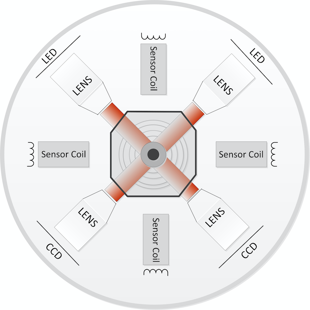 The Eccentricity Gauge combines electromagnetic and optical scanning principles. The optical scanning system is used to define the wire insulation outer diameter and the electromagnetic system is used to determine the wire core position, eccentricity and 8 point wall thickness.
Optical measurement is done by sending out light from LEDs which shine on the measuring object thus casting a shadow on the CCD receiver. The image information is then evaluated by integrated signal processors.
The optical measurement and magnetic measurement are performed simultaneously at high rates, minimizing inaccuracies caused by wire vibrations, and both measurements are controlled on the same plane to eliminate the errors due to product twists.
Electrical and Operating Requirements
| Power Supply | Power Consumption | Operating Temperature | Environmental Protection |
| 85 to 274 VAC | 300 Watts | 5 °C – 45 °C (41 to 113 °F) | IP65 |
Size & Weight
| Height 1166 mm (45.9”) |
Depth 360 mm (14.2”) |
Width 142 mm (5.6”) |
Weight 45 kg (99 lbs) |
 |
Industry 4.0
 |
More than 200 Data Words are available to communicate with your Industry 4.0 Solution. Data Words are divided the into distinct function groups to make it easy to select the ones you want. |
| Gauge ID Data Words | Model Number, Serial Number, Firmware APP version, Firmware Core Version, Firmware Date |
| Calibration Data | Last Calibration Date, Days Since Last Calibration, Total Run Time, Calibration Alarm |
| Validation Data Words | SNR, Signal Amplitude, Good Readings, FFT Amplitude |
| Wired Network Info | IP Address, Netmask, Gateway |
| Wi-Fi Network Info | IP Address, Netmask, Gateway, SSID |
| Measurement Data | Diameter, Eccentricity, Eccentricity Angle |


